Thursday, March 3, 2016

Very Interesting new project on Pi


Here's a project that is very interesting. I will be keeping an eye on this.

https://ultibo.org/

Its a bare metal compiler for the Pi, that lets you run code right on the hardware. No operating system.

I made a video of the boot. 1 second boot. Pretty neat.


The compiler looks very easy to use. If they keep working on it, and get everything working, this will be really interesting. Especially with a Pi Zero, or Pi3 model A. You get all the hardware of a modern day computer, and the ease of a microcontroller. Its like having a microcontroller running at 1GHZ and having multicore with multithreading.

This is from the examples, #12. Its a webserver, has a dos shell, controls the LCD, has access to the ethernet port and can create an HTTP socket, has access to the SD card.


Sunday, February 21, 2016

Git Hub repository for design

Hi folks.

I've created a Git hub repository for the design files and code for the robot.

Here it is: --> https://github.com/fixstuff/MDRobot

Inside the "Board Files" folder, there are the gerber and design files for the Teensy-based PLC mother board.

Inside the "Source Code" folder, there is the Codesys Project archive, which includes libraries.  This archive is in 7 parts, due to Github size restraints.  Also in this folder is the python script for accessing the GPS data on the Ultimate GPS hat, and the Teensy sketch for the I2C slave and interfacing functions.

There is a lot of good stuff here.  For example, the Codesys project includes my custom device parameter file that allows a generic I2C driver to talk to many different I2C devices.  To date, I've tested over 20 different I2C devices.  Included with the project is code to talk to the Teensy I2C slave, and the Adafruit 10 DOF IMU.  There is also code to talk to the 4 ch I2C DAC chip on the PLC motherboard.  All of this uses that I2C driver.

There is also good code samples in the project including the GUI with embedded video, Modbus client and slave access code, access to the Linux system from Codesys, Real time Clock functions, building automation functions, Serial port access functionality, just to name a few.

The Teensy sketch is useful also.  It uses the I2C slave library, and demonstrates several useful techniques such as task management using elapsed millis, and other tricks.

The gps python script is useful as well, since I added a Modbus TCP data interface to pass the GPS data into the Codesys via Modbus.  This is useful in several ways.  It can allow you to transfer information from Linux into the Codesys runtime (since there is no SDK), and this can be used both locally, or over a network.  This same mechanism can be used for any code running in the Linux system, not just Python, you would simply download the widely available open source Modbus libraries available for whatever language you need.  This is a very easy way to bring data into Codesys on the Pi.

I will be adding more folders as I go along.  The next folders will be the power subsystem, the Metal detection subsystem, and the control subsystem.

Monday, February 15, 2016

Next Steps

All right.

I've finally decided to move the PC back into the bot.  I have decided to put Windows on the PC, versus Debian.  This will eventually allow me to run a Kinect 2 on the PC along with Microsoft Azure and .Net. I want to really start getting up to speed on this - I might even use another Pi with Win 10 Iot on it to try it out - I want to keep up with it as well.

This will also allow me to do something else.  I can keep all of my development packages on this PC, and simply VNC into it for development.

I will also run a SQL database on the PC for a historian, and also support a GUI running MS Azure.  I will interconnect to the Pi running Codesys with the Windows PC using Modbus TCP initially, and perhaps OPC UA later.

This will also allow me to run a Secomea Sitemanager, and even a PC version of Codesys as a supervisory machine.

I will run a full time Modbus server on the machine, and will run Bonjour on it as well and run a Phidget webservice server on it.

This will be the next major addition for now.  Only one downside.  The minimum hardware requirements for the Kinect 2 is a 64 bit dual core 3GHZ class machine with USB 3.0.  My little Zotac HTPC is not at that level....  I think an Intel NUC is in the cards..

More ESP8266 tinkering

Well,  I have found a couple weak spots in the ESP8266 arsenal.  The big one is I2C.  I have set up a link between a Teensy and the ESP without any trouble.  However, when I started using the ESP alone, that's when I started seeing problems.  It looks like certain I2C devices don't play nicely with the ESP's I2C capabilities.  I found one with the BNO055 Absolute orientation sensor.  I was able to test it just fine with the Teensy alone, but had all kinds of trouble with the ESP8266, particularly with the on-board watchdog timer.  I could power up the unit, and the program would run, but would only get readings for about 10-20 seconds or so.  I narrowed it down to the BNO055 calibration routines, it "auto-calibrates", and once it switches over to a more calibrated state, the I2C comms go to hell.  I seem to have narrowed it down to the I2C on the ESP8266, and I saw a lot of other postings on this exact same issue.  There were some updated Wire libraries that supported I2C clock stretching, which according to some folks, the BNO055 seems to need.  I couldn't get the new Wire library working unfortunately, maybe I'll give it another try later.

Here's a screenshot of where it stops working.  It works for a bit and then it just stops.  I haven't put an oscope to it, it's not worth it to me yet to screw with it too much more.

Good feedback right up until calibration shows 3's..


Saturday, February 6, 2016

Remote Pendant Idea and others

I've been playing around with my code for the Teensy/Huzzah/Codesys Pi system.

I can already see several uses for this exact setup.

One use, for me on the robot is a remote pendant.  This to me is a perfect fit, with just enough I/O and capability to give me a nice wireless controller for the robot with a serial display.

I had thought about a Pi as the pendant, but I was limited in the hardware IO for reading a quadrature encoder and analog inputs - I would have had to add another MCU like a Teensy or something anyway.

For about the cost of the Pi alone, I can have the whole assembly for under about $40.

I can see a lot of use for that as a pendant for any number of projects.

Another idea for this is a remote wireless encoder.  I can take a Teensy and a Huzzah with a quadrature encoder, and have wireless position feedback fairly easy.  Something like this, which is pretty much a similar idea: https://hackaday.io/project/8118-programmable-wifi-control-knob.  I think I can fit them in the end housing of the motor also..

I can see a ton of use for this.  Remote temp sensing, keypads, you name it.

End housing for motor.  Alternate motor mounting anyone?

Friday, February 5, 2016

Latest Huzzah news

Ok.

I've had some time now to play around a bit with the Huzzah ESP8266.

I'm pretty darned impressed with this chipset.  Again, I am also impressed with Adafruit on the development board its on.

That being said, I also found some of the things I'm not so crazy about.


There is no PWM available direct off the board, which was disappointing.  Its also a tad bit delicate, with it occasionally only reading in Modbus registers and ignoring sending out any.  I minimized this somewhat by slowing things down a bit, but it can be somewhat aggravating.  It appears to be the Modbus library for the ESP8266.  Its not the most robust library for sure.  I had to get creative on the Codesys side, to not hammer the little guy to hard.  I did get it working though with both reading and writing registers.

Since I had no PWM, and only 1 weird 10 bit A/D, I added a "helper" in the form of a Teensy 3.1.  Using the Huzzah's I2C bus, I expanded the I/O greatly using the Teensy as an expander.  I now have 4 ch of analog, digital inputs, outputs, and a couple PWM channels configured.  It's pretty much wide open now with the Teensy.  It just doubles the complexity and triples the price. Yay!.  Its still only about $30 from a measly $10.

So, now I have a full wireless Wifi sensor node, that can also do distributed control.  I can still use just a Huzzah for simple on/off, and analog feedback from sensors, but this setup here is the full deal.  I still can use the Teensy RTC, for a standalone controller with real time clock capabilities.  With a Codesys Pi "brain", I can control everything from a nice, centralized master controller with GUI interface.  Overall its pretty nifty.


Test setup with Codesys web HMI, Huzzah, Joystick, and Teensy and PPDB.

Adafruit Huzzah ESP8266 board

Teensy 3.1

2 axis joystick

Codesys Online view and Huzzah's serial debug view


Thursday, February 4, 2016

Robot Overlords

Thought of something last night.

I have my robot, sitting on stands, minding it's own business.  I connect to it's router, in order to debug and program it, using the Codesys IDE.

Now with this new remote sensor/actuator tool, in the form of a cheap Huzzah ESP8266 Wifi and Modbus TCP connectivity, I can have the robot connect to a device in my house, and do stuff.

One of my todo projects is a reflow oven.  I was debating throwing in a simple controller like a Teensy, Arduino, whatever, ordering a TC sensor module, solid state relays, all that stuff.  Mount the controller.  Mount the LCD.  Add some buttons.  Write some code in C or whatever, tie it to expensive TC sensor modules, and a solid state relay or two.  All of this hardware is now tied up for one purpose.  The oven.  Between $100 and $150 no problem.

Now I'm thinking, "I could have my robot run my reflow oven"...  It would be trivial.  Take an AD595 TC amplifier, sample it from the 10bit 1.8V Huzzah A/D, transmit the temp to the PLC on request, and turn on/off a solid state relay when the PLC directs it.  I have a temp profile state-machine running in the PLC, that ramps up, soaks a bit and does the solder temp spike.  I could even set up a nice GUI I could access from my mobile phone whenever I want to solder something.

Take this a step further, and just mount the Codesys Pi PLC brain, ANYWHERE.  Plug it in the wall.  Set it on the table.  Stick it in a closet.  Put it on your head (No, don't do that). Don't care.  Now, you have a controller that can run anything in your house.  A reflow oven.  A light controller.  A security system.  Anything.

Makes my head spin.

Wednesday, February 3, 2016

Codesys Pi Modbus Client polling a Modbus Server in an ESP8266 Huzzah

I've had a couple of these Adafruit ESP8266 Huzzahs laying around, but I hadn't had the time to mess with them.

I took the time tonight, and I'm glad I did.

Using the Arduino IDE, I flashed a "sketch" onto the Huzzah, that not only gives me the ability to run Arduino libraries, but I found a Modbus Server library that works with it from here:

https://github.com/andresarmento/modbus-esp8266

It worked!  I was able to set up a Modbus client on the Codesys running on the Pi, and could poll a running counter coming in on register 0.

Adafruit ESP8266 Huzzah running Arduino sketch with Modbus server library
This may not be so useful with the robot, but is super useful for remote sensing duties.  I would like to try using this for a "smart" metal detecting coil array, that houses the electronics on the coil, and transmits via Modbus TCP to my PLC over Wifi.  Think smart house with central PLC controller and a mesh of sensors feeding data.

Heres a screenshot.  Note the latency difference in numbers... I can speed this up somewhat, but I will have to tweak it.

Codesys online displaying values from Huzzah connected over Wifi via Modbus TCP

More finishing work

Hi folks.

I've added some new mounting hardware to the system.

I moved the IMU outside the box in a non-conductive/magnetically isolated sensor "pod".  The IMU was getting interference from all of the internal magnetic fields, and now looks good.  Heading behaves like it should.  This is the white PVC.

I purchased three SMA M-F extension cables, and routed the Wifi router antennas outside the controls enclosure.

I mounted the GPS antenna externally as well, with the external GPS cable.

I secured the batteries to the side of the battery enclosure, using two eyebolts and a ratcheting strap.  I added a rubber mat underneath the batteries to minimize slipping, and added a rubber mat to the lid, in case something heavy pushes it in while closed.

Finally, I added a couple more mounting bars to the chassis wheel frame, so that I can remove the top square frame, and keep the wheel frame hard mounted.  It's easier to remove the top square frame in order to open the two enclosure lids fully.

On a software note, I successfully utilized Codesys's command line access capability.  I made the Python script that decodes and displays the GPS data, and writes to the Pi's Codesys Modbus server the GPS latitude and longitude, using the Pymodbus library.  I then made the script executable, and ran the gpsd daemon process call and script call from inside Codesys.  This allows Codesys to run the Modbus server first, then run the two GPS programs.  Otherwise, running the script to early without the server running will terminate the script with an connection exception.  That is actually a big piece of the control scheme - it allows me to run any Linux code, and pass return arguments back into Codesys.

Here are some pictures...


Shows the new antenna mounts and IMU pod.

Router view. note the antenna extensions.

top view of power supplies

caster wheel view.  I will add the other bar when I get in the 45 brackets on order.  Then I can remount the top square - maybe with a hinge.

batteries and rubber lid mat. note the blue ratchet strap holding the batteries to the wall.

Another front view. note the two eyebolt nuts on the right enclosure.

Batteries.  Note the ratchet on the right side of the batteries.

Another lid view. Note the GPS cable the feeds through the top of the lid.  May end up moving the router inside somewhere on a wall if I need room.


Saturday, January 30, 2016

Rebuilt Caster mounting bracket

I rebuilt the caster mounting bracket for the new frame mounting.  Its much more sturdy now for sure.  I will remove the hinge pin on the lids maybe to make access easier.  With this new frame arrangement, I'm considering moving the controls on the lid up to another enclosure on the next level.  Ugg.  I have to do this anyways for the metal detector controls, so I guess i can move the others.  This will make the bottom strictly power, batteries, and motor drives.

On another note, it looks like the cheap Harbor Freight caster isn't going to work very well. I guess I'll look into using those pillow blocks I bought way back.  They might be better for the swivel.

I also noticed my video was lagging quite a bit lately.  Not sure if its the GPS daemon causing the issue or not.  I'm guessing its a file access bottleneck to the SD card.  Two ways to approach it if that is the case - use a separate non-video Pi for the GPS, or remove the onscreen video.

I also weighed the bot with the added framing.  It weighs in at 282 lbs...


Wednesday, January 27, 2016

Added Upper frame for detector controls

Whew!

I added the upper 80/20 frame, which will support the detector electronics.  I will hinge the upper treadplate, which allows me to open both access doors on the drive and power controls about 50%.  This will also give me the added support for the swivel which will now mount to both the upper and lower frame sections.  Having it on the bottom only, had too much flex.

Pulling the right corner to mount a strut

Left corner..

Finished right corner strut mounting

Upper and lower frame

Both frames with treadplate cover.

Tuesday, January 26, 2016

Added GPS to bot

I got the GPS positioning up and running!

I received the Adafruit GPS Hat I ordered, which is this https://www.adafruit.com/products/2324.

I also ordered the stackable header  https://www.adafruit.com/products/2223, so that I can plug the ribbon into the HAT board now, instead of the Pi.

I ordered the SMA to uFL adapter:
https://www.adafruit.com/products/851,

the external GPS antenna:
https://www.adafruit.com/products/960,

the coin cell battery:
https://www.adafruit.com/products/380,

the standoffs https://www.adafruit.com/products/2336

I soldered the stackable header, installed the board with no issues.  I installed the gpsd daemon that Adafruit detailed in the nice online guide, and I used the python code from Dan Mandle's blog here:
 http://www.danmandle.com/blog/getting-gpsd-to-work-with-python/.

In order to bring the data into Codesys, I wanted to pass the data values into the Codesys Pi's Modbus server, so I installed the pymodbus library from here:
 https://github.com/bashwork/pymodbus

Using the library's payload builder and client's write registers function, I was able to successfully get the data from the GPS into the Codesys.

This is the same method I will eventually use for the Phidget modules I will need as well eventually, since there is a ton of python code out there for that as well.  I could end up compiling and running it in C, but I like the simplicity of using the Python, and speed in this case isn't an issue.  We'll see what works out better later.

Here are some pictures...

Adafruit Hat GPS plugged into Pi


Screenshot of GPS Data


Saturday, January 23, 2016

Voltage / Current sensing added

Last night and today, I added the voltage sensing circuit, and current sensing circuits.  Not happy about the current sensing, turns out my sensors are rated too high (600A) sensors, to get enough resolution sensing the low current of the bot.  Oh well, I have to price out some smaller ones.  I had these laying around and hoped I could use them.

I've also been looking at the frame.  I knew the swivel was more or less temporary, but I have a plan now.  I will go ahead and mount the 2nd part of the frame above the box height, and connect the two frames by 4 connecting beams.  I will attach the swivel bracket to a cross member attached to both frames.  This should double the strength and rigidity, and also double my mounting space on the rover.  I will need this room up top for the detector control enclosure and the other hardware.

Below are picts of the new wiring and sensors, and a new screenshot.


New voltage and current sensors

Latest screenshot without meters and more info

Tuesday, January 19, 2016

Added the Estop and power switch circuit

Hi folks!

I've added the Estop and Power On/Off circuit.  With this I can run the bot on the ground (hopefully).

Here are some new pictures of the mods.  Below are videos I posted also..

Estop and Power Contactors with Estop button and Power On/Off.

Rear view Left

Right side lid open


Rear View Right

cell phone browser GUI screen


Friday, January 15, 2016

Rover update

Hi folks,

I haven't updated in a while, so I thought I would post some of the latest pictures and info.

I have changed the rover setup somewhat from the original plan.  Originally, I was going to use an onboard generator, to power a 120V power circuit, since I had lots of 120V powered hardware.

I have modified that a bit.  I added two, 12V batteries in series for 24V.  I also added a 24V inverter to power the onboard electronics, along with a battery tender charger, that is designed to be left in the circuit all of the time.  This allows independant, "quiet" running off of batteries, and still retain the ability to charge off a generator for long term field use.

I have several power supplies running for 12V, 5V, and low power 24V (isolated from batteries), on the 120V power circuit.  Without much of a load, the power supplies only pull 32VA on the power circuit, or 0.28A.  The inverter can supply up to 600W so I should have plenty of room.

I am using a puresine type inverter, to give me the cleanest AC power I can get.  I had a modified sine wave type earlier, and one of my power supplies was wining about it, so I changed over to the true sine wave.  No more wining from the power supplies.

I also have the SoftPLC with the Codesys running on my base board installed.  I am driving the Sabertooth 2X25 motor drive board from 2 of the DAC outputs on the baseboard.  This seems to work really well.  The base board is running the Adafruit 10DOF IMU, which gives me pitch, roll, and yaw, with Heading.  I also have temp and barometric pressure with altitude from this as well.

I have a Pi camera embedded in the control GUI, to steer by, if needed.  I have also upgraded the Wifi Router to an uptodate TPLink AC1750 Dual Band Gigabit router.  This gives me plenty of range, and bandwidth for streaming video and control.

I still have to install my main power on/off circuit, and my ESTOP circuit before I can run on the ground.

Still to do is adding the ROS computer.  I had originally planned on the Zotac HTPC, but I will be changing over to an Intel NUC or equivalent, and run ROS from that.  The plan is to bring in ROS-specific sensors such as the Kinect, and run a Modbus server, to pass data from the SoftPLC based Pi.

I still have to build the detector array, as well as the Main Operator Console which I havent started on yet.  I could use a laptop for this, and run everything from the broswer GUI, but I really like actual hardware.  I had planned on using another Pi with the 7" touchscreen display, running another SoftPLC and Codesys - using the Pi hardware, and perhaps another base board for this.   However, I would use the laptop with Windows 10 and run another gui with a SQL database historian from it.  I can run a USB server on the ROS machine, and have access to Phidgets and other USB based hardware in the rover from the Windows machine.  This would allow me to use my Phidget GPS and other boards I bought.

I guess that's it, I'll post more later. :)

Below are some pictures of the various hardware, and a screenshot of  a basic rover motor control GUI.

Screenshot of Motor Control GUI

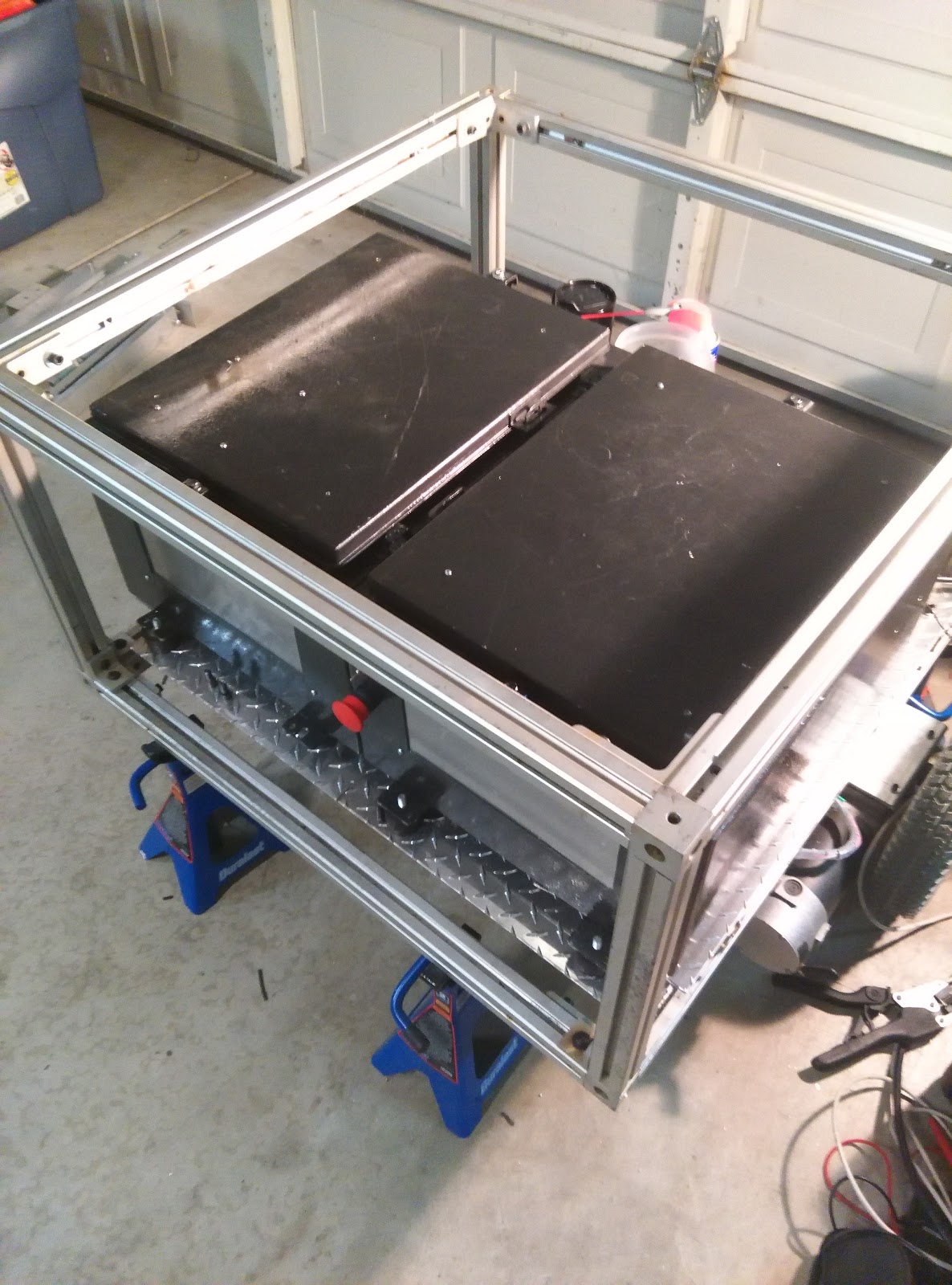
Right side view of Rover with lids open

Left control bay showing batteries, inverter, and charger.

Left bay again

SoftPLC running Codesys on the Pi and baseboard with Sabertooth 2x25 and Wifi router